 Successful system design is heavily dependent on the designer’s understanding of the channel and its properties. Tait Principal Engineer Ian Graham continues his radio theory series with examples of channel properties that are critical to overall RF system design.
In a radio system, there may be large distances (including hills, forests, buildings etc) between the transmit and the receive antennas. This is the channel, the medium over which we propagate the signal from the transmitter to the receiver. Here we look at nine key channel properties that it is important to understand.
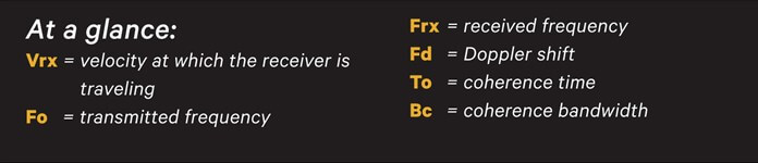
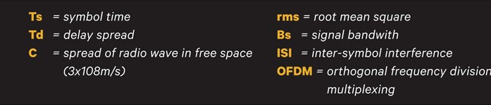
However, before we start, explanations of a few symbols and terms we’ll be using:
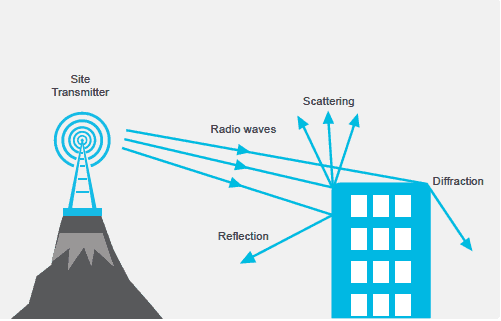
1. Reflection, Diffraction and Scattering
Reflection occurs when a radio wave hits a smooth surface that is much greater than a wavelength and effectively bounces off.
Diffraction (or shadowing) occurs when the path between the transmitter and receiver is blocked by a dense object that is much greater than a wavelength, forming secondary waves behind the obstruction. It is also known as shadowing.
Scattering occurs when a radio wave hits either a rough surface or a surface with dimensions of a wavelength or less, causing reflected energy to scatter. Typical scatterers are lamp posts, street signs and foliage. This means a transmitted signal usually reaches the receiver via several different paths, known as multipath propagation.
Because these multiple copies of the transmitted signal travel different distances and arrive at the receiver at slightly different times, they can either add or subtract, and cause fluctuation in the received signal strength. This is multipath fading.
The two main types of multipath fading are Rayleigh Fading and Rician Fading.
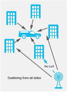
2. Rayleigh Fading
Rayleigh Fading occurs when the received signal consists only of multipath components – there is no line of sight signal. It is common where there are many tall buildings. Fades tend to be short, but very ‘deep’, so the received signal strength varies by over 30dB in very short time intervals.
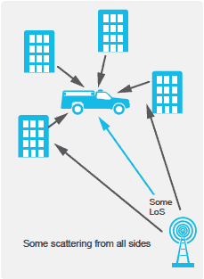
3. Rician Fading
Rician Fading occurs when the received signal consists of both line of sight and multipath components. Rician Fades tend to be short, and because the line of sight signal is the strongest, received signal strength variations (the ‘depth’ of the fades) are less than Rayleigh Fading, typically around 10dB.
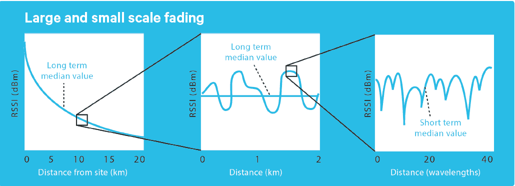
4. Large Scale and Small Scale Fading
Fading can be categorized as either large or small scale fading. Large scale fading describes the slow changes in received signal strength due to traveling over large areas. Shadowing can cause this. Rayleigh and Rician Fading are small scale fading, where the received signal strength varies dramatically over very small distances. A mobile-equipped vehicle traveling a large distance experiences large scale fading with small scale fading superimposed. The following diagram illustrates this.
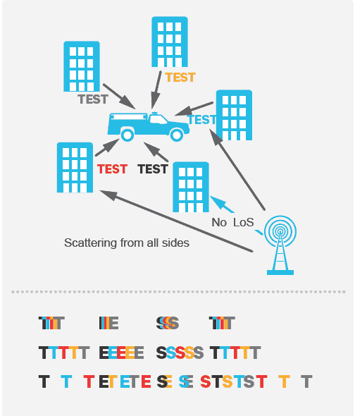
5. Delay Spread
The time difference between the arrival of the first multipath component of the signal and the last (which will have arrived via a different path) is known as Delay Spread.
Obviously, if a signal is received at a given time, and then a replica of that signal is received a fraction of a second later, the information will ‘blur’. As the delay spread increases, quality of the received audio degrades and eventually communication is lost, even when the signal level is above the receiver’s sensitivity level.
In the first line, the multipath components of the signal S1, S2, S3, S4 and S5 all arrive at the receiver within a short time. While there is some degradation, the information is still understandable. In the second line, delay spread increases and it is harder to understand. In the third line, delay spread exceeds symbol time and communication is lost.
6. Doppler Shift, Doppler Spread, Coherence Time and Fading Rate
These three properties are closely related.
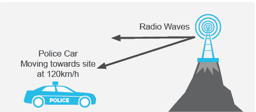
Doppler Shift
The simplest illustration of Doppler Shift is the increase in the frequency of the engine note you hear when a car drives towards you, and the decrease you hear once it is moving away. The same effect happens with radio. Doppler Shift is the change in frequency that occurs when a vehicle receiver is moving towards or away from the transmitter.
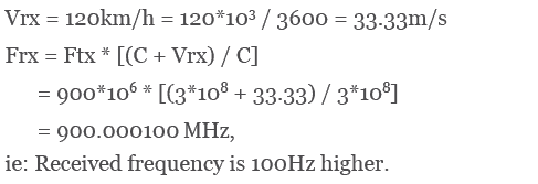
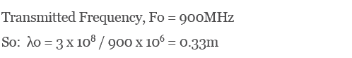
Take the example of a receiver moving toward a transmitter operating at 900MHz.
As the receiver is moving towards the transmitter, Vrx is +ve, so:
Doppler Spread
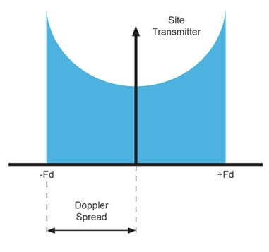
When a receiver is moving in a multipath environment, the frequency of the multipath components we are heading towards appear to increase; the frequency of the multipath components we are heading away from appear to decrease. Frequency spreading of the received signal is called Doppler Spread.
If the received signal multipath components come from all directions with equal power, a plot of the received power at each frequency in the received signal would look like this:
Coherence Time
This is the duration for which the channel doesn’t change noticeably. The Doppler Spread (Fd) and the Coherence Time (To) are reciprocally related. The approximate relationship between the two parameters is:
![]()
For example: the Rayleigh Fading envelope of a received signal at 900MHz is shown in the diagram.
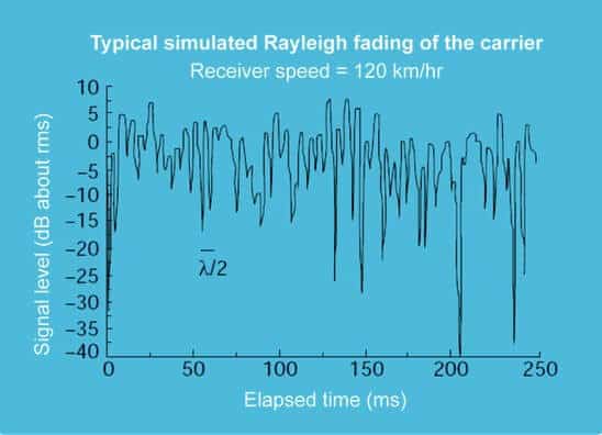
The distance traveled corresponds to two adjacent small-scale fades and is roughly half a wavelength. From this, we can work out both the Coherence Time and the Doppler Spread.
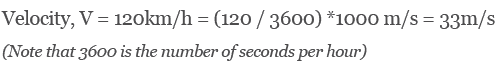
The receiver is traveling at 120km/h, so:
Because the distance traveled by the receiver between fades is about half a wavelength, the coherence time is time taken to travel this distance. So we can express coherence time as:

Now we know the Coherence Time, we can calculate the Doppler Spread:
![]()
Fading Rate
This is the number of fades an object travels through in one second. The greater the fading rate, the greater its destructive effect on the received signal. Fading rate is a function of frequency; the lower the operating frequency, the higher the speed of the object before communication is lost. So for high speed trains that travel at some 300km/hr a lower frequency gives best RF operation.
7. Fast and slow fading
These are caused by the receiver moving towards some multipath signal components and away from others.
Fast Fading
Corresponding to Doppler Spread is the concept of Coherence Time, effectively the time duration over which the channel is flat. It is inversely related to Doppler Spread, Fd:
![]()
If the baseband signal varies more slowly than coherence time, ie: Ts > To, then distortion from Doppler spread fading is significant, because the channel condition has changed significantly in the time taken to transmit one symbol. This is fast fading: if you are traveling fast, you experience a rapid change in channel condition.
Slow Fading
Conversely, if the baseband signal varies faster than the coherence time, (Ts < To), distortion from Doppler spread fading is negligible. Slow Fading is when the channel condition has not changed significantly within the time taken to transmit one symbol.
Intuitively, if you are traveling slowly, you experience a slower change in channel conditions.
8. Coherence Bandwidth
The Coherence Bandwidth is the bandwidth over which the channel conditions don’t change, where two multipath components of the received signal have strong potential for correlation.
Coherence Bandwidth (Bc) is related to delay spread so if Td is the rms delay spread, then:
![]()
9. Flat and Frequency Selective Fading
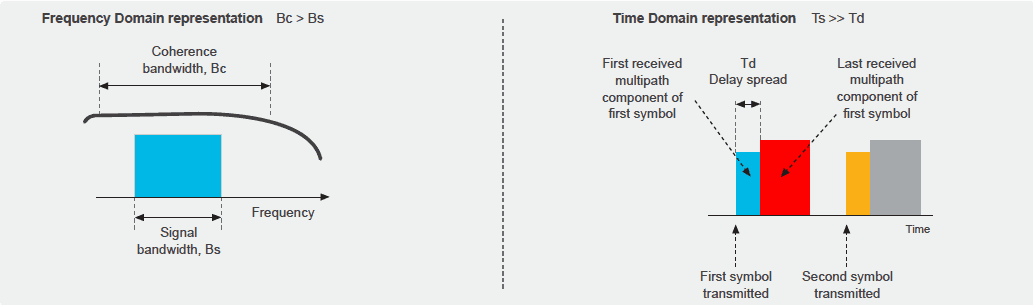
Flat Fading
Flat Fading occurs where all frequencies within the signal experience the same fading. It occurs if the symbol time is much greater than delay spread, so all multipath components arrive well within the symbol time. Another way of looking at it is flat fading occurs when coherence bandwidth is greater than the signal bandwidth. The coherence bandwidth over which the channel is considered flat is greater than the bandwidth of the signal.
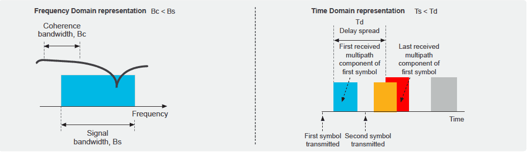
Frequency Selective Fading
This occurs where different frequencies within the signal experience different levels of fading. In the time domain, it occurs when symbol time is less than delay spread. The delay spread is so long that components containing the next symbol are received before all the components containing the previous symbol, causing inter-symbol interference (ISI).
In the frequency domain, it occurs when coherence bandwidth is less than signal bandwidth. The coherence bandwidth is less than the signal bandwidth, so different frequency signal components experience different fading.
If you think that this is a problem for a broadband signal, you’re right. This is why LTE systems use OFDM techniques. Rather than transmitting on very wide band signal modulated at a high symbol rate, the broadband signal is divided into many slowly modulated sub-carriers. These sub-carriers then only experience flat, rather than frequency-selective fading.
 This article is taken from Connection Magazine, Issue 6. Connection is a collection of educational and thought-leading articles focusing on critical communications, wireless and radio technology.
Share your views, comments and suggestions in the Tait Connection Magazine LinkedIn group.